Standing Desk Controllers - Reverse Engineering and Making A Custom One
This project was originally done in late 2022.
Project files can be found here
Not too long after purchasing a used no-name generic standing desk from a local listing, the controller spontaneously stopped working. Faced with what was now, well, just a desk, I felt incredibly stupid having paid for the standing feature.

The standing desk in question has no identifying features or even labels to help me give you an idea of whether or not these solutions will work for you. Instead, I’ll describe all my learnings and contexts so that, if they don’t exactly match, you’ll at least be able to replicate it yourself.
User Interface
The little control-box only interacts with the user with two simple capacitive touch buttons. When it worked, they would debounce for what felt like an unnaturally long time, about a second, and then begin traveling in the direction of the button arrow. No presets. Just up and down.
Reverse Engineering
This section is split into two main sections.
- Cables and Connectors
- Electrical Schematic
Once we have an idea of how the controller works, I just wanted to design my own interface around it, so I didn’t care to look into any firmware.
The Cables and Connectors
- AC/DC 19V at 3A to cable-cable connector
- cable-cable connector to a cable-board connector
Cable-Cable Connector
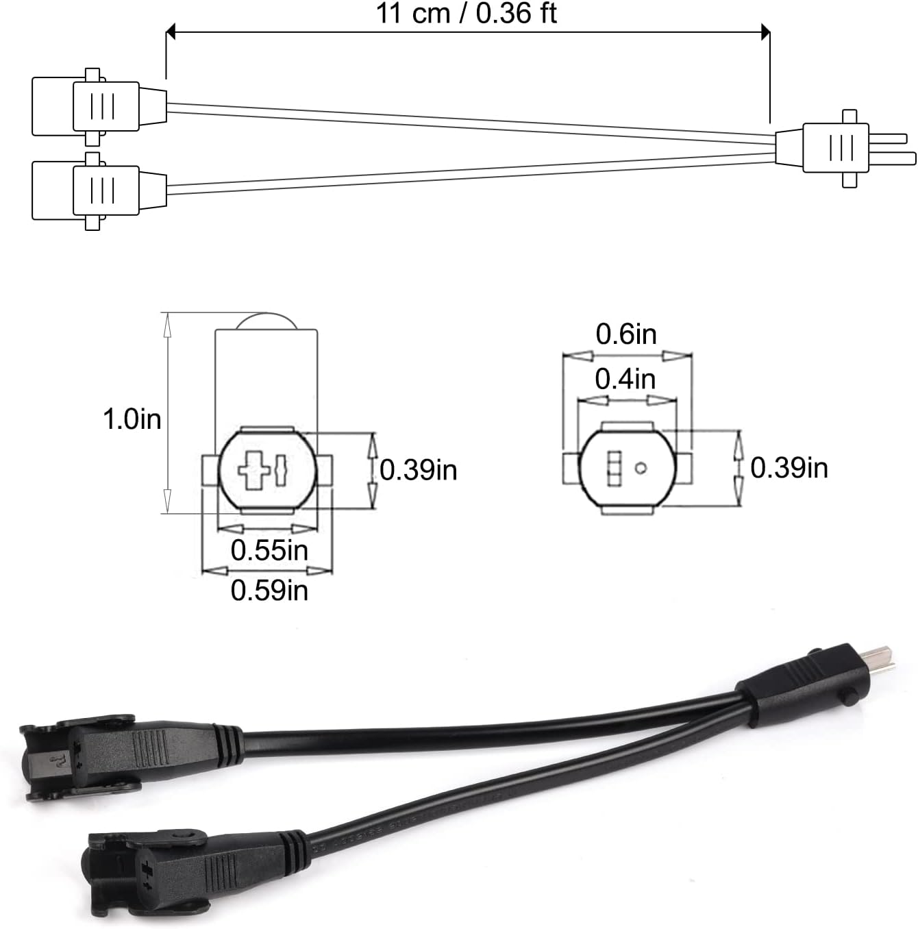 Ignore the splitter - this is the correct cable headers. This is simply for illustration purposes
The pinout were two parallel metal prongs, one of which was significantly larger than the other. This male prong then was inserted into a female receptacle, which itself had a small hinged arm that you could rotate around the male receptacle thus securing it in place.
This female receptacle then itself had some nice rubber strain relief and a little box surrounding the cable that allowed it to be placed into the small plastic enclosure.
Cable-Board Connector
 Render of the cable-board connector
The cable then finally terminated into a plastic snap-in connector that had a matching receptacle on the PCB itself. This connector is a nice and widely available TE-Connectivity Part Number 1744429.
Electrical Schematic
So we have 19V to the PCB. Here’s where it goes
- 19V to two relays. The relays themselves are configured to make an H-Bridge. Both of them are by default connected to GND, such that when one coil is energized, current flows FROM that to the motor.
- 19V to a simple buck converter for the logic
Local Logic
This brings us to the motor. My particular desk uses a DC motor. This was actually not incredibly intuitive to determine until I popped open the little control box. To assemble the desk, you connect the power into the box, and then the motor to the box as well. The motor uses a 6-pin connection. This pinout is described later.
Anyway, we now have a solid idea of what voltages and currents are used and where they go.
Reverse Engineering - The Motor (And Encoder)
The motor pinout confused me. Why would we need 6-pins to control a DC motor? Were half of them the supply and half ground just for the current-carrying capability? The motor itself also included a neat little pulse-based encoder!
Before describing everything, here’s the pinout I found on my particular desk.
Looking at the female receptacle.
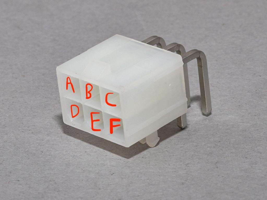
| Letter | Function | Notes |
|---|---|---|
| A | Encoder 1 | Encoder output #1 |
| B | Motor 1 | Motor power supply |
| C | Motor 2 | Motor power supply |
| D | Encoder VCC | Supply voltage to encoder |
| E | GND | GND for encoder |
| F | Encoder 2 | Encoder output #2 (inverted) |
These sorts of motors employ very simple encoders - each rising edge denotes one unit of rotation. Encoder 2 is an inverted version of Encoder 1. It’s pretty simple, we are basically counting ‘steps’ to know where the motor - and therefore desk surface - are.
The encoder also conveniently comes with it’s own supply, meaning we don’t have to worry too much about safely converting that signal to a low voltage to be read by our microcontroller. That being said, in my first design, it’s clear that I was not certain of this. In fact, I wasn’t certain at all of the behavior of either pin at all.
One thing worth mentioning was that the calibration process would simply drive the desk to it’s lowest position, where the motor would then stop because it ran into a stop, and the current would jump. This jump in current was somehow detected, and the bottom was set. It would then remember the number of steps upwards and downwards and not let the desk hit the very bottom.
In my second design, I kept some input protection. Something about sending 19V at 3A into a DC motor in the same connector as my little dainty logic-level encoder outputs just screamed inductance and voltage spikes, and I’d love to not have to debug a fried digital pin some years from now.
Now that we’ve effectively reverse engineered the basic functioning and I/O of the box, let’s discuss my design
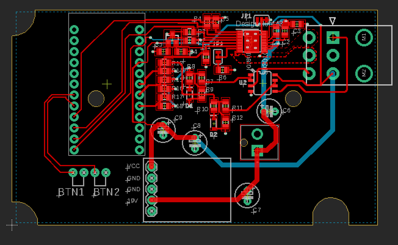
Engineering A Replacement - Version 1
Here’s the schematic I came up with in my first version. Here are the highlights.
MCU
A no-name amazon atmega32u4 arduino-leonardo/mini. I directly added in the socket to just solder this entire module onto my PCB because I couldn’t be bothered to integrate the MCU on board. Also, it’s cheaper to do this way. 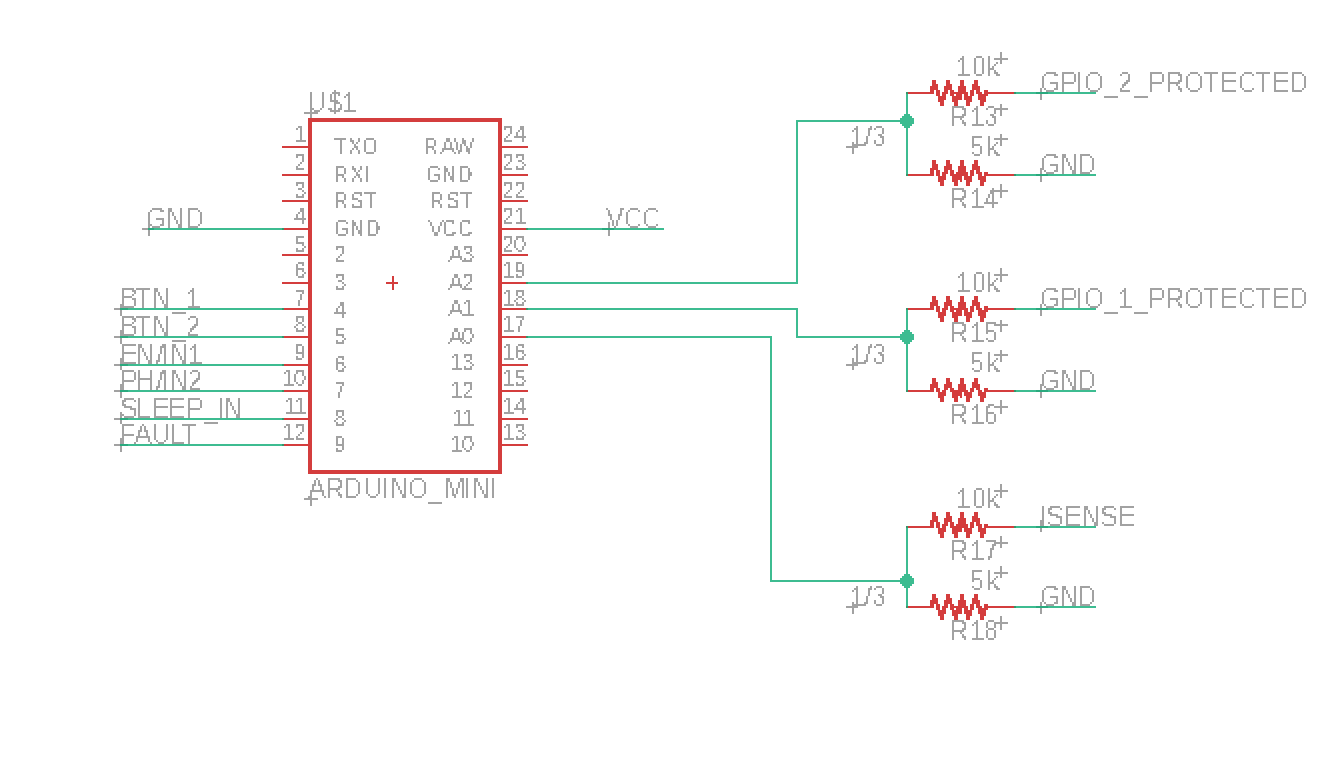
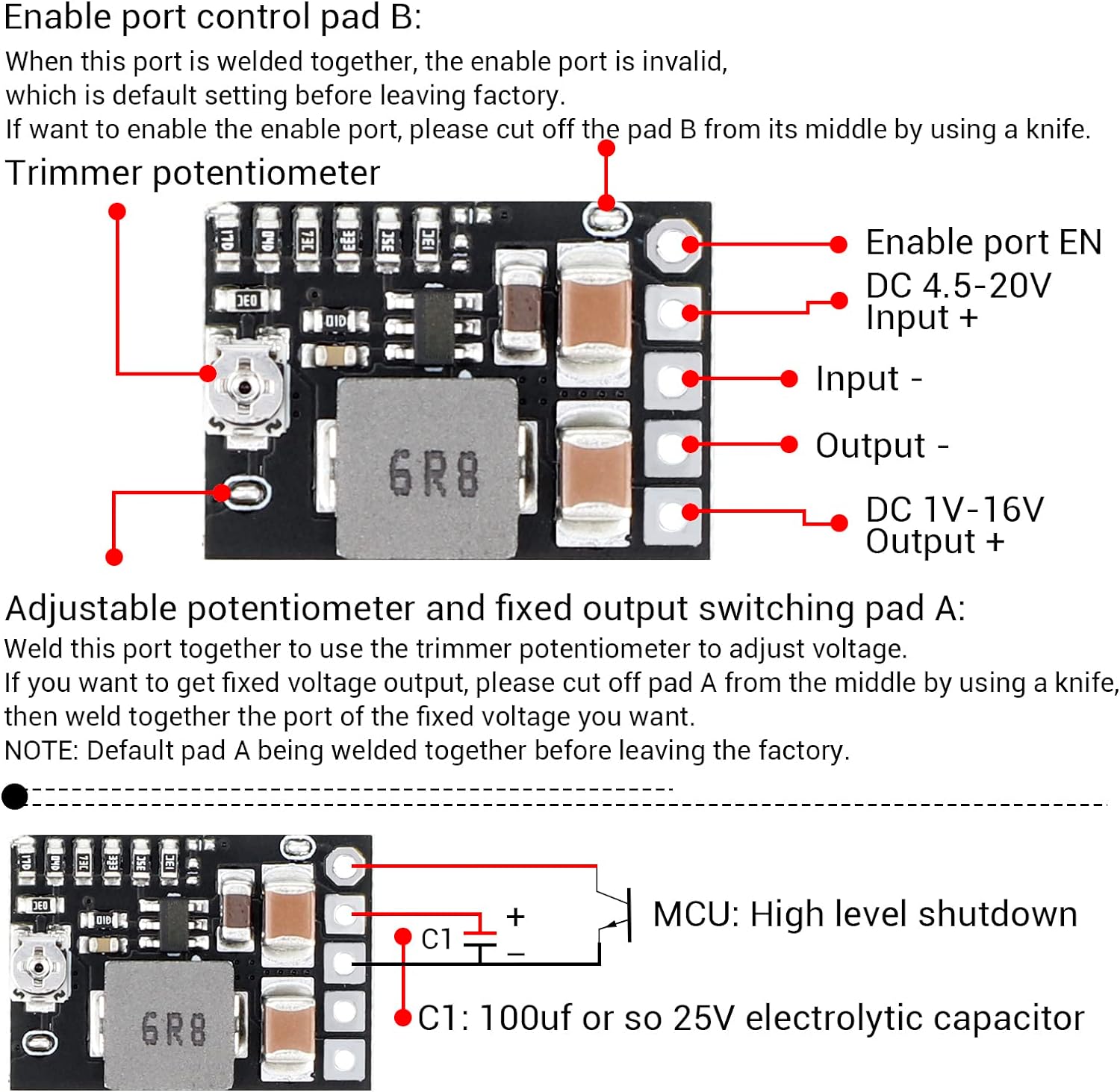
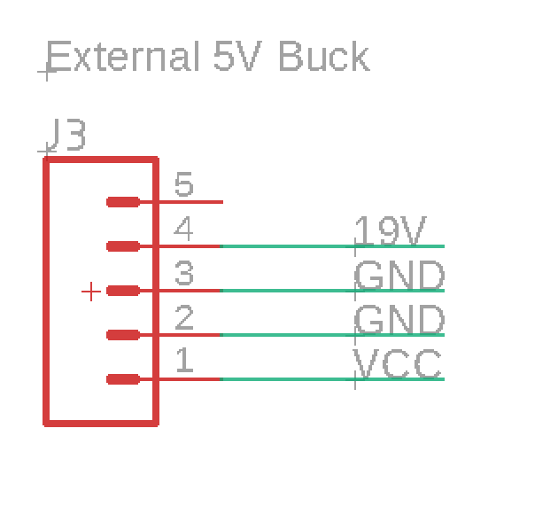
Power
Note we need to generate a local 5V supply from the 19V. In a similar vein as above, this is simpler and cheaper. It’s also less things to go wrong. It’s a all-in-one buck converter board - another amazon cheapie. Plus, now I’ve got 4 extra!
The Motor Driver
I went with the DRV8876 H-Bridge Motordriver from TI becaue of its availability, price, and seemingly simple integration. With at 3.5A peak current drive, I thought this would be perfect. It also promised integrated current sensing, so I could do calibration.
I planned to use the fault pin, or the analog output for current sensing, to detect the bottom of the range of the desk for calibration.
Spoiler, I actually found this IC a total pain in the ass to integrate and debug, and it ended up not working at all either. 3.5A peak-current is nowhere near high enough to start such a chunky DC motor, and this IC features a fast latch-off for overcurret conditions.
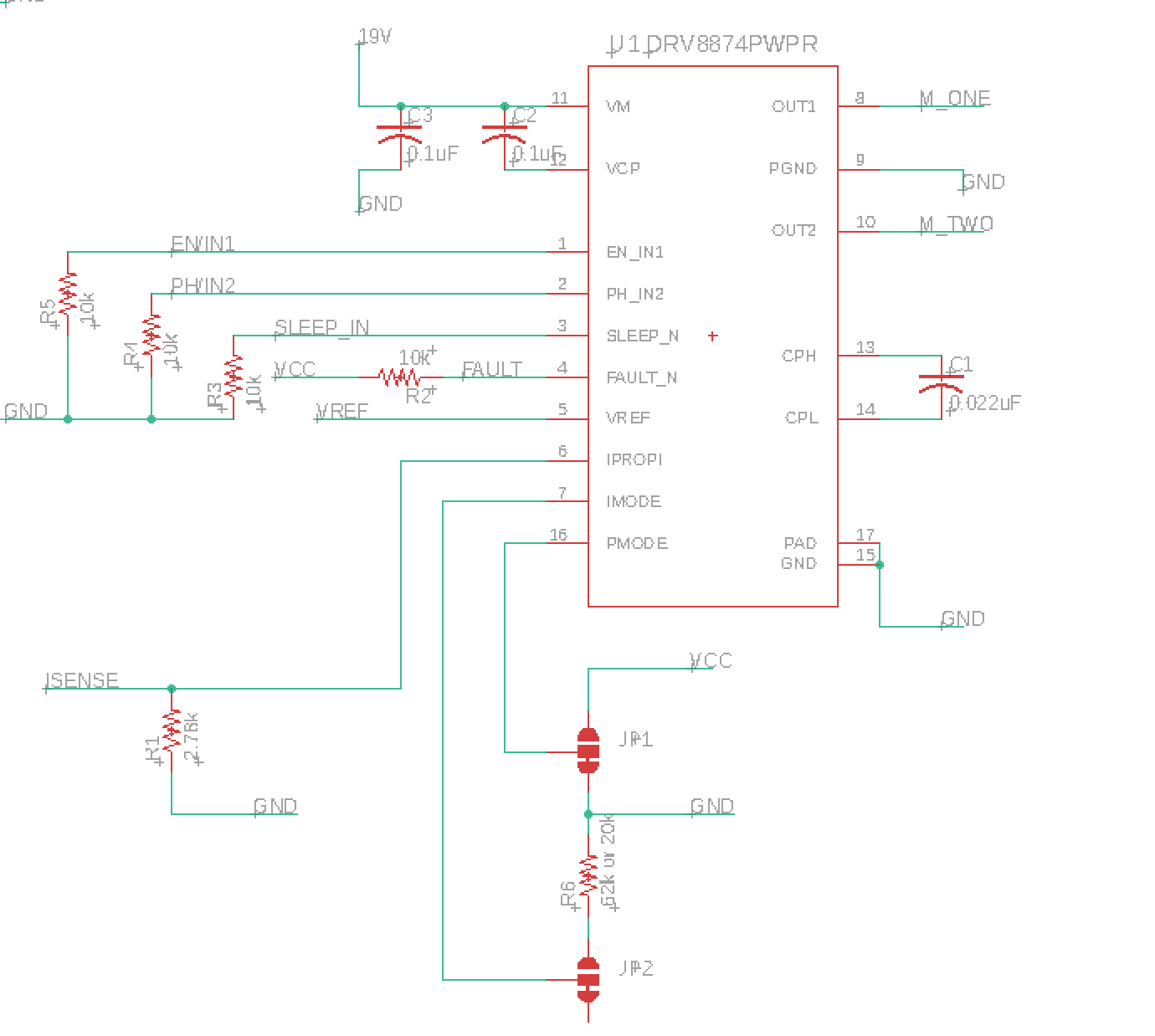
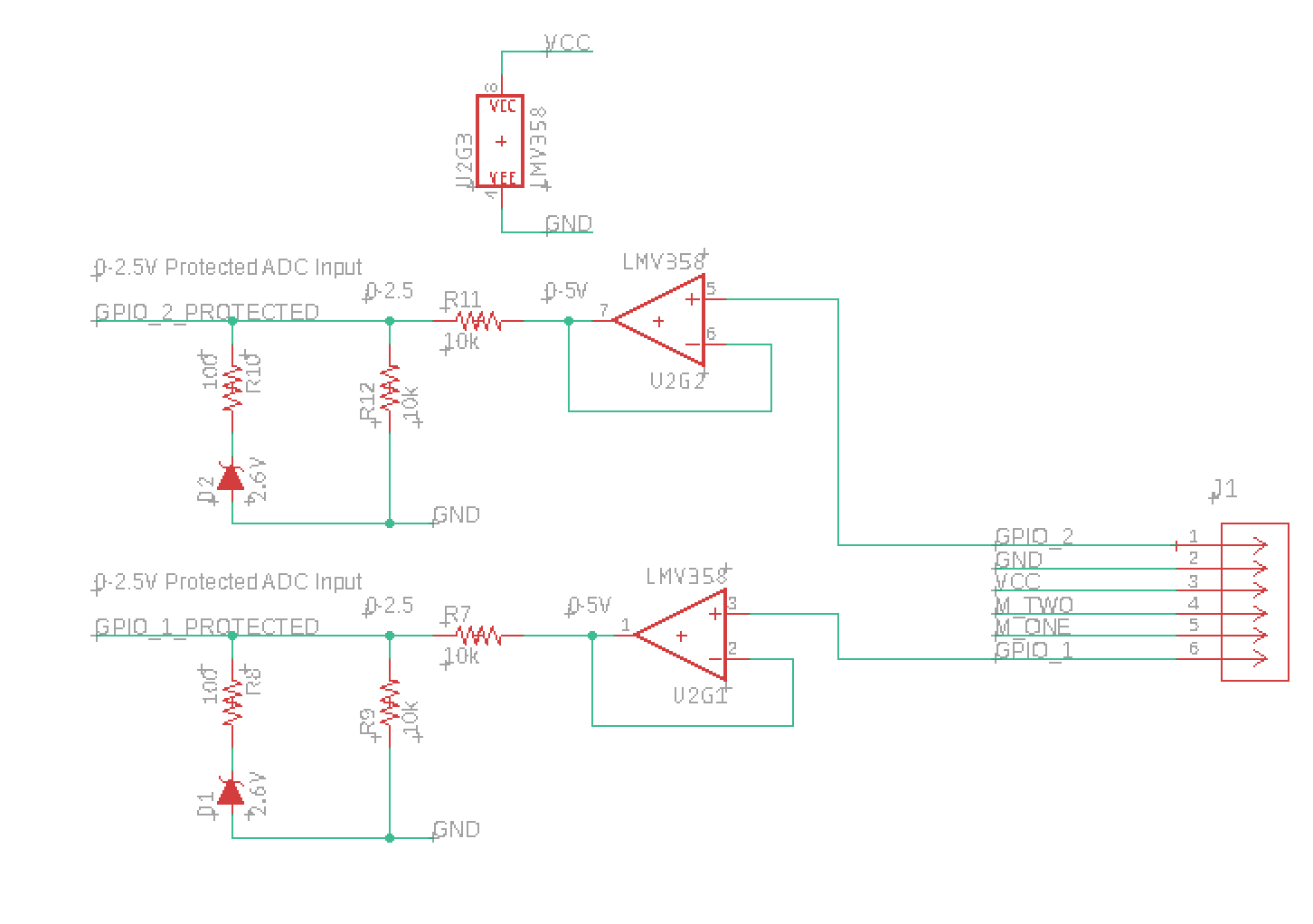
Encoder and Input Protection
This is what I consider to be the most interesting part of this version.
Why all the input protection? Hindsight is 20/20. We needed this input protection because I was not sure what GPIO1 or GPIO2 did, and I did not bring in this controller box to my lab to fully reverse engineer it, nor did I probe the signals while the motor was active.
I was confident enough that the encoder was isolated from the motor power supply, but inductive spiking from the motor starting or stoping scared me. Those are nasty bugs to track down, because they can happen somewhat randomly and fry hardware without any indication.
So we needed to basically clamp the voltage to VCC - which was 5V. F
- Op-amp with negative-feedback - an analog isolator: This was the first step in input protection. If the voltage spiked on any GPIO pin, the rail-rail potential of the amp itself was oly 5V, so our output of the op-amp could (theoretically) not go above 5V.
- Voltage Divider: Halves our 5V max from the op-amp to 2.5V, which itself is well within the Arduino’s adc range.
- A 2.6V Zener Diode: As a last line of defense, when a voltage of 2.6V is across the zener diode, it will begin to conduct current, which will then create a large voltage drop across the 10K resistor from the voltage divider, effectively clamping it.
- Another Voltage Divider (not pictured): In the MCU seciton, you may have noticed some extra 1/3 voltage dividers. These again step down the 2.5V to 0.83V maximum. Also, in the worst case of the op-amp failing to short the positive input to the output, and the zener diode failing, we would have only the remaining voltage dividers. A 1/2 ratio to a 1/3 ratio means a total ratio to the ADC from our GPIO pin would be 1/6. 19V is our maximum expected voltage here (ignoring inductive spiking), which would result in no more than 4V at the ADC.
The Voltage Reference?
Yea… This one is funny and in hindsight totally unnecessary. It was a super cheap part, and I thought it was a good idea to make sure we keep the needed reference voltage of the DRV8876 precise, as we are dealing with a lot of potential noise on our power rails.
The full schematic
Here is Version 1 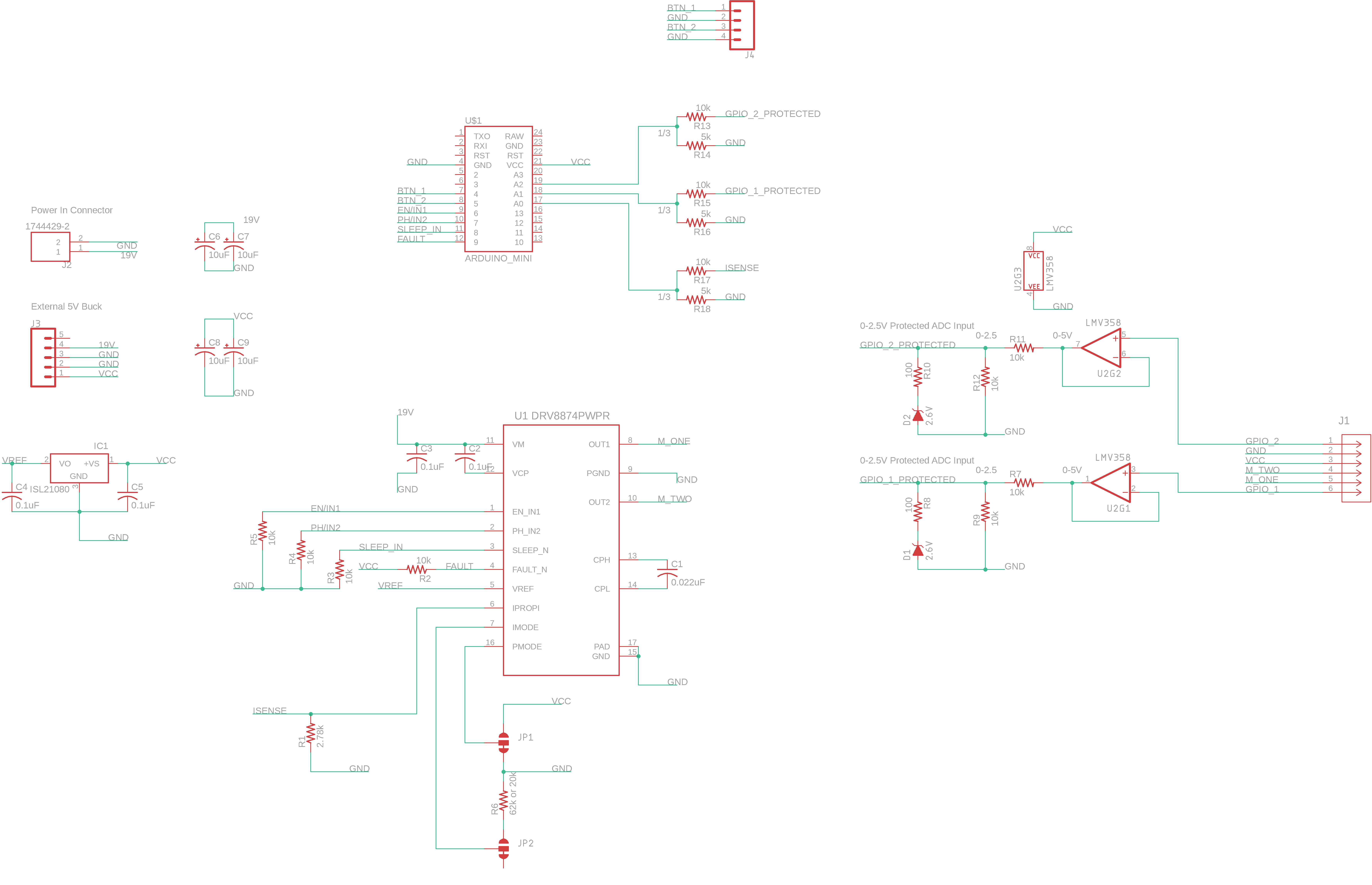
Results
This first version of the board did not work as hoped.
| Function | Status | Notes |
|---|---|---|
| Physical footprint | OK | All connectors were correct and the board profile slotted perfectly into the existing ABS case |
| Power | OK | This is why I went with a daughterboard module - worked great |
| Motor | FAIL | Motor driver would not drive the motor. It would stutter. I deduced that it was the current limiting kicking in on startup, because the motor would never drive upwards, and would stutter driving downards until it eventually gained enough momentum and would finally continuously drive. Safe to say current sensing also didn’t work, as the IC was latching off frequently due to overcurrent. |
| Input Protection | OK | I was able to plot the analog signals from GPIO1 and GPIO2 to see their waveform while manually shorting 19V to one of the motor terminals, forcing it to drive. This confirmed that they were logic-level 5V encoder signals, and nothing high-voltage or analog |
Objectives for the next design
- Functioning motor driver with high-peak current
- Current sensing for the motor
- Reduced input protection for the GPIO pins
Engineering A Replacement - Version 2
A New Motor Driver
Rather than butt my head against overengineered motor drivers, I thought I’d take a page directly out of the original design and use relays. These are much simpler to use, and no pesky overcurrent conditions will get in our way. TODO:
Current Sensing
I did not have an idea of the exact current the motor would consume in different conditions, so I had to use a current sensing solution that was robust across a wide range. Note: now that I do have an idea, though, we could easily just use a differential amplifier across a shunt resistor with a jellybean op-amp and then feed the output referenced to ground to an analog pin.
I chose the INA250A2 because it had a builtin shunt resistor which made my life a little easier. The output voltage from the INA250A2 is 0.5v/A with a 5V full range output. This meant we could sense up to 10A.
Input Protection
I did away with the op-amps from the original design. On second thought, if we had a transient, the op-amps could become damaged and either short or not pass any signal at all. Instead, I just used a voltage divider and the zener diode clamp. These two in combination would safely clamp any transients from the inductance of the motor. I also removed the extra 1/3 voltage reduction at the MCU itself because it was unneccessary.
Schematic photo TODO:
Results
This revision worked flawlessly! Nothing to note here. Let’s talk about the software
Control Software
The Idea
Using only the two buttons, up and down, I wanted to implement a box with the following functions
- Ability to set on-the-fly presets
- Two presets
- Go-to a preset
Here’s how the UI works
| Input | Action |
|---|---|
| Press and hold up button | Go up |
| Press and hold down button | Go down |
| Double-press up button | Go to the top preset |
| Double-press down button | Go to the bottom preset |
| Press and hold both buttons | Set current position as our safe ‘zero’ position |
| Fast press both buttons | Set current position as a preset |
When we fast-press both buttons, if we are currently above the bottom preset, our old top preset becomes our new bottom preset, and our current position becomes our top position, and vice-versa. It may seem unintuitive, but this is what I felt made the most sense after going through a few iterations on the UI structure.
The Code
We first import EEPROM and setup our defines for our GPIO. top_steps is an arbitrary number that I determined to be the number of steps from the bottom of range of motion
zeroReference and curCurrent are actually not used for anything meaningful. They were meant to store values from the current sensor, but I realized I don’t actually need any current sensing so long as I’m responsible.
If we are giving power to the motor, but the motor is not moving as indicated by pulses, we are at the bottom!
topPreset and botPreset are simply global variables where we set our presets
Finally, the last three variables are all global variables that we update between functions, and they are self explanatory.
Note that
stepsis by default the same astop_steps. We do this so that the user is forced to move the desk down until hitting the botom, at which point we calibrate. If we lose power at the top, the user could incidentally drive the desk too high and off of it’s rail.
1
2
3
4
5
6
7
8
9
10
11
12
13
14
15
16
17
18
19
20
21
22
23
#include <EEPROM.h>

#define DEBUG 1

#define BTN_1 4
#define BTN_2 5
#define m_one_ct 6
#define m_two_ct 7

#define currentsense A2
#define steppin 3

#define top_steps 2250

float zeroReference = 0;
float curCurrent = 0;

int topPreset = -1;
int botPreset = -1;

bool movementDirection = 0;
bool isCalibrated = false;
long steps = 2250;
Before the helper functions or main control flow, let’s talk about the setup. I do the standard serial declaration and pin direction setting. We attach an interrupt on the rising edge to one of our GPIO pins. Lastly, I set zeroReference and curCurrent to the analog reading from the currentsense pin, unnecessarily.
The interrupt calls step_counter which increments or decrements our global current position counter depending on the direction that we are traveling.
1
2
3
4
5
6
7
8
9
10
11
12
13
14
15
16
17
18
void setup() {
  if(DEBUG) Serial.begin(9600);
  pinMode(BTN_1, INPUT_PULLUP);
  pinMode(BTN_2, INPUT_PULLUP);

  pinMode(m_one_ct, OUTPUT);
  pinMode(m_two_ct, OUTPUT);

  attachInterrupt(digitalPinToInterrupt(steppin), step_counter, RISING);

  zeroReference = analogRead(currentsense);
  curCurrent = analogRead(currentsense);
}

void step_counter(){
  if(movementDirection) steps +=1;
  else steps-=1;
}
Below are our helper functions.
These are self-explanatory and uninteresting.
1
2
3
4
5
6
7
8
9
10
11
12
13
14
15
16
17
18
19
20
21
22
23
24
25
26
27
28
29
30
31
32
33
34
35
36
37
38
39
40
41
42
43
44
45
46
47
48
49
50
51
52
53
54
55
56
57
58
59
60
61
62
63
64
65
66
int difference(int place){
  //Returns a negative number if current place is less than steps - WE ARE BELOW REQUESTED
  //Returns a positive number if current place is greater than steps - WE ARE ABOVE REQUESTED
  return (place - steps);
}

void goTo(int place){
  if(steps < place){ //current pos is below - need to go up
    Serial.print("Driving up to ");
    Serial.println(place);
    while(steps < place){
      motorForward();
    }
    motorStop();
  }
  else{
    Serial.print("Driving down to ");
    Serial.println(place);
    while(steps > place){
      motorBackward();
    }
    motorStop();
  }

}

bool btnOnePressed(){
  return (digitalRead(BTN_1) == LOW);
}
bool btnTwoPressed(){
  return (digitalRead(BTN_2) == LOW);
}

void driveUpward(){
  if(steps <= top_steps){
    motorForward();
  }
  else{
    Serial.println("At limit!");
  }
}
void driveDownward(){
  Serial.println("Running");
  if(steps >= 20){
    motorBackward();
  }
  else{
    Serial.println("At limit!");
  }
}
void motorForward(){
      movementDirection = 1;
      digitalWrite(m_two_ct, HIGH);
      digitalWrite(m_one_ct, LOW);
}
void motorBackward(){
    movementDirection = 0;
    digitalWrite(m_two_ct, LOW);
    digitalWrite(m_one_ct, HIGH);
}
void motorStop(){
  digitalWrite(m_two_ct, LOW);
  digitalWrite(m_one_ct, LOW);
  delay(100);
  zeroReference = analogRead(currentsense);
}
Now, let’s discuss the main control loop.
To determine whether or not a button was pressed, pressed-and-held, or double-pressed, we do the following.
- Wait for a button press
- Grab the state of both buttons at this instant and start a timer
- We then wait for
HOLD_THRESHOLDtime - We continue waiting while our timer has not expired, or both buttons are not pressed
If the elapsedTime is too long, we ignore the button press. This doubles as a convenient debounce.
Valid button presses - basically their initial and final states, and the time between them - now make it to line 23
We again break into a few different conditions
if(bTwoFinal == 1 && bOneFinal == 1)4 If we end our window, and the buttons are still both being held down, we continue to determine if we are ‘pressing and holding’ the two buttons as the same time, or if we just pressed them both for an instantelse if(elapsedTime > HOLD_TO_DOUBLE_THRESHOLD)If we end our window, and our button press events happened close enough together, then we are confident we had a double-press. We then choose whether or not to go to our top preset or bottom preset depending on which one was double pressed.elseFinally, if all else fails, and we end our window with a single button being pressed outside of ourHOLD_TO_DOUBLE_THRESHOLD, we know it was ‘pressed and held’.
1
2
3
4
5
6
7
8
9
10
11
12
13
14
15
16
17
18
19
20
21
22
23
24
25
26
27
28
29
30
31
32
33
34
35
36
37
38
39
40
41
42
43
44
45
46
47
48
49
50
51
52
53
54
55
56
57
58
59
60
61
62
63
64
65
66
67
68
69
70
71
72
73
74
75
76
77
78
79
80
81
82
83
84
85
86
87
88
89
90
91
92
93
94
95
96
97
98
99
#define HOLD_THRESHOLD 100
#define IGNORE_THRESHOLD 400
#define HOLD_TO_DOUBLE_THRESHOLD 150
void loop() {

  //Wait for a button press
  while(!btnOnePressed() && !btnTwoPressed());//Serial.println("Waiting for first press");
  unsigned long startTime = millis();
  bool bOneInitial = btnOnePressed();
  bool bTwoInitial = btnTwoPressed();

  delay(HOLD_THRESHOLD);

  while((!btnOnePressed() && !btnTwoPressed()) && (millis()-startTime < IGNORE_THRESHOLD + 100));//Serial.println("Waiting for second press");
  unsigned long endTime = millis();
  bool bOneFinal = btnOnePressed();
  bool bTwoFinal = btnTwoPressed();

  unsigned long elapsedTime = endTime - startTime;
  if(elapsedTime > IGNORE_THRESHOLD){
    Serial.println("Too long between presses... ignoring");
  }
  else{

    if(bTwoFinal == 1 && bOneFinal == 1){
      int elapsedTime = 0;
      while(btnOnePressed() && btnTwoPressed() && elapsedTime <= 200){
        elapsedTime++;
        delay(1);
      }
      if(elapsedTime > 200){
        Serial.println("Bottom set");
        steps = 0;
        delay(500);
        motorForward();
        delay(200);
        motorStop();
      }
      else{
        if(steps > topPreset){ //If steps > top preset -> this pos is top prest
          botPreset = topPreset;
          topPreset = steps;
        }
        else{
          botPreset = steps;
        }
        if(botPreset < 15){
          botPreset = 15;
        }
        if(topPreset < 15){
          topPreset = 15;
        }
        if(botPreset > 2250){
          botPreset = 2250;
        }
        if(topPreset > 2250){
          topPreset = 2250;
        }
        Serial.println("Custom set");
      }
    }
    else if(elapsedTime > HOLD_TO_DOUBLE_THRESHOLD){
      Serial.print("Double Press: ");
      if(bTwoFinal == 1 && bOneFinal == 0){
        Serial.println("Left Button");
        Serial.print("Going to bottom preset ");
        Serial.println(botPreset);
        goTo(botPreset);
      }
      else if(bTwoFinal == 0 && bOneFinal == 1){
        Serial.println("Right button");
        Serial.print("Going to top preset ");
        Serial.println(topPreset);
        goTo(topPreset);
      }
    }
    else{
      Serial.print("Single/Hold Press ");
      if(bTwoFinal == 1 && bOneFinal == 0){
        Serial.println("Left Button - move downwards");
        while(btnTwoPressed()!=0 && steps >= 15)
          motorBackward();
        motorStop();
        if(!(steps >= 10)) Serial.println("At bottom limit");
      }
      else if(bTwoFinal == 0 && bOneFinal == 1){
        Serial.println("Right button - move forwards");
        while(btnOnePressed()!=0 && steps < top_steps)
          motorForward();
        motorStop();
        if(!(steps < top_steps)) Serial.println("At top limit");
      }
    }
  }
  Serial.println("-------------");
  while(btnOnePressed()!=0 || btnTwoPressed()!=0);
  Serial.println("Done");
  motorStop();
}
The full code can be found in the github repo!
Conclusion
I’m happy with what I’ve now got - there are a few functional improvements in the schematic and code that I can absolutely implement. However, it’s functional and I can’t be bothered to really change much.
All the files are here on github. Each revision includes the BOM, schematic, board, and Arduino Code.